

EMC Test Items
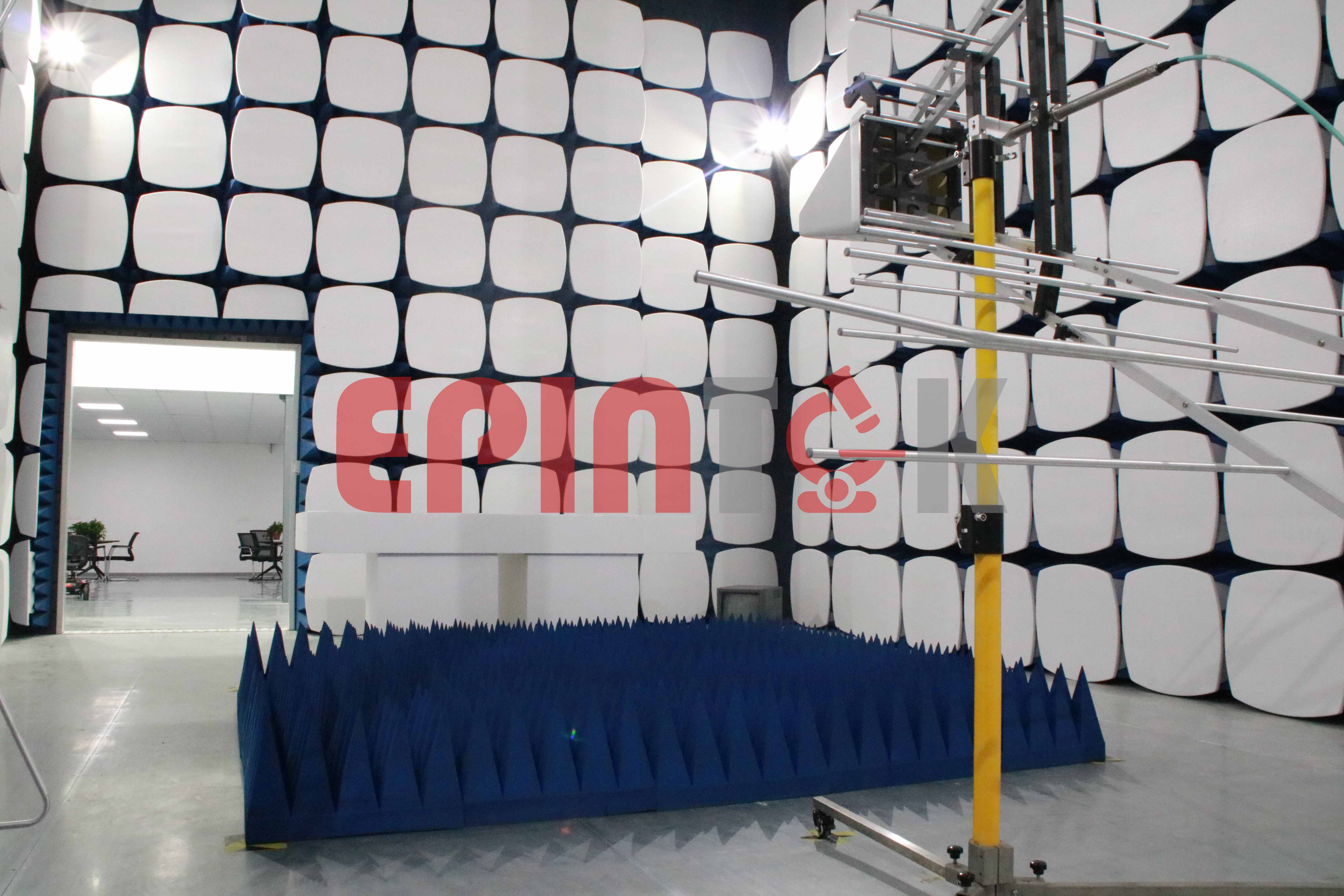
EPINTEK EMC Lab is accredited by A2LA, IAS and CNAS to ISO/IEC 17025 and maintains one 3 meter EMC/EMI test chamber, shielding room and three testing rooms to meet customer’s EMC and EMI testing requirements. We are always looking for new ways to improve our service offering whether that's new labs, new EMC test equipment, or new EMC compliance processes and systems.


Introduction of EMC test items
EPINTEK EMC Lab is accredited by A2LA, IAS and CNAS to ISO/IEC 17025 and maintains one 3 meter EMC/EMI test chamber, shielding room and three testing rooms to meet customer’s EMC and EMI testing requirements. We are always looking for new ways to improve our service offering whether that's new labs, new EMC test equipment, or new EMC compliance processes and systems.
With one EMC testing center located in Suzhou, EPINTEK goes beyond testing to provide customers with professional consultation and technical support throughout the EMC testing and market approval process.
The main capabilities include Medical products, Household Appliances, Consumer Electronics, Wearable devices, Wireless products and Industrial, Scientific and Medical Devices, Measurement & Laboratory Equipment, etc.
Also, we mainly focus on providing customers with professional EMC project testing and Debug services.
· EMC test items | · EMI · (Electro Magnetic Interference) | · Conducted emission | · Conducted Emissions is a term for radio frequency current that flows on one or more conductors connected to an electric circuit, or alternatively, radio frequency voltage between conductors connected to an electric circuit. Generally, conducted emissions voltage is specified as the voltage that develops when conducted emissions current encounters a 50 ohm impedance. · For the purposes of EMI analysis, conducted emissions are generally of interest over the frequency range 150 kHz to 30 MHz, because this is the frequency range over which most regulatory agencies specify conducted emissions limits. |
· Radiated emission | · Within the field of EMC, the term Radiated Emissions refers to the unintentional release of electromagnetic energy from an electronic device or apparatus. Any electronic device may generate Electromagnetic fields that unintentionally propagate away from the device’s structure. In general, Radiated Emissions are usually associated with non-intentional radiators, but intentional radiators can also have unwanted emissions at frequencies outside their intended transmission frequency band. As was discussed in the EMC Regulations module, the allowable Radiated Emissions from electronic devices and apparatus are regulated by various organizations and agencies. Electronic devices that have significant amounts of radiated emissions may interfere with their normal operation or the normal operation of other devices in close proximity. For these reasons, it is important to understand the concepts behind the origins of radiated emissions so that fundamental design techniques can be used to minimize the emissions. This module will investigate the origins of radiated emissions, and discuss methods to predict, measure, and minimize the radiated emissions from an electronic device. Differential Mode (DM) and Common Mode (CM) currents will be introduced, and their roles in radiated emissions will be investigated. Using current probes to measure the differential and common mode currents on current carrying wires will be discussed. Finally, a discussion will be given on the role of circuit geometry and device structure on the radiated emissions from an electronic device. | ||
· Disturbance power | · The measurement of disturbance power using an absorbing clamp is a method for the determination of the radiated disturbance in the frequency range above 30 MHz. This measurement method represents an alternative approach to the measurement of the disturbance field strength on an OATS. The absorbing clamp measurement method (ACMM) is described in Clause 7 of CISPR 16-2-2. | ||
· Harmonic distortion | · This part of IEC 61000 deals with the limitation of harmonic currents injected into the public supply system. · It specifies limits of harmonic components of the input current which may be produced by equipment tested under specified conditions. · This part of IEC 61000 is applicable to electrical and electronic equipment having an input current up to and including 16 A per phase, and intended to be connected to public low-voltage distribution systems. · Arc welding equipment which is not professional equipment, with input current up to and including 16 A per phase, is included in this standard. · Arc welding equipment which is not professional equipment, with input current up to and including 16 A per phase, is included in this standard. · For systems with nominal voltages less than 220 V (line-to-neutral), the limits have not yet been considered. | ||
· Voltage fluctuations and flicker | · This part of IEC 61000 is concerned with the limitation of voltage fluctuations and flicker impressed on the public low-voltage system. · It specifies limits of voltage changes which may be produced by an equipment tested under specified conditions and gives guidance on methods of assessment. · This part of IEC 61000 is applicable to electrical and electronic equipment having an input current equal to or less than 16 A per phase, intended to be connected to public low-voltage distribution systems of between 220 V and 250 V line to neutral at 50 Hz, and not subject to conditional connection. · This part of IEC 61000 is applicable to electrical and electronic equipment having an input current equal to or less than 16 A per phase, intended to be connected to public low-voltage distribution systems of between 220 V and 250 V line to neutral at 50 Hz, and not subject to conditional connection. | ||
· EMS(Electro Magnetic Susceptibility) | · Electrostatic Discharge | This standard relates to equipment, systems, subsystems and peripherals which may be involved in static electricity discharges owing to environmental and installation conditions, such as low relative humidity, use of low-conductivity (artificial-fiber) carpets, vinyl garments, etc., which may exist in all locations classified in standards relevant to electrical and electronic equipment (for more detailed information, see IEC 61000-4-2 Clause A.1). NOTE From the technical point of view, the precise term for the phenomenon would be static electricity discharge. However, the term electrostatic discharge (ESD) is widely used in the technical world and in technical literature. Therefore, it has been decided to retain the term electrostatic discharge in the title of this standard. | |
· Radiated RF EM fields | Electronic equipment can, in some manner, be affected by electromagnetic radiation. This radiation is frequently generated by various sources, such as small hand-held radio transceivers, fixed-station radio and television transmitters, vehicle radio transmitters and industrial electromagnetic sources. Many of these services use modulation techniques with a nonconstant envelope. In addition to electromagnetic energy deliberately generated, there is also radiation caused by the operation of devices such as welders, thyristors, fluorescent lights, switches operating inductive loads, etc. Conducted electrical interference is dealt with in other parts of the IEC 61000-4 series. Methods employed to prevent effects from electromagnetic fields will normally also reduce the effects from these sources. In this document, the electromagnetic environment is characterized by the strength of the electromagnetic field. The field strength is not easily measured without sophisticated instrumentation nor is it easily calculated by classical equations and formulas because of the effect of surrounding structures or the proximity of other equipment that will distort and/or reflect the electromagnetic waves. | ||
Electrical fast transients/bursts | The repetitive fast transient test is a test with bursts consisting of a number of fast transients, coupled into power, control, signal and earth ports of electrical and electronic equipment. Significant for the test are the high amplitude, the short rise time, the high repetition frequency, and the low energy of the transients. The test is intended to demonstrate the immunity of electrical and electronic equipment when subjected to types of transient disturbances such as those originating from switching transients (interruption of inductive loads, relay contact bounce, etc.). | ||
Surges | Power system switching transients Power system switching transients can be separated into transients associated with: a) major power system switching disturbances, such as capacitor bank switching; b) minor local switching activity or load changes in the power distribution system; c) resonating circuits associated with switching devices, e.g. thyristors, transistors; d) various system faults, such as short-circuits and arcing faults to the grounding system of the installation. Lightning transients The major mechanisms by which lightning produces surge voltages are the following: a) direct lightning stroke to an external (outdoor) circuit injecting high currents that produce voltages by either flowing through ground resistance or flowing through the impedance of the external circuit; b) indirect lightning stroke (i.e. a stroke between or within clouds or to nearby objects which produces electromagnetic fields) that induces voltages/currents on the conductors outside and/or inside a building; c) lightning ground current flow resulting from nearby direct-to-earth discharges coupling into the common ground paths of the grounding system of the installation. The rapid change of voltage and flow of current which can occur as a result of the operation of a lightning protection device can induce electromagnetic disturbances into adjacent equipment. | ||
Conducted disturbances induced by RF fields | The source of disturbance covered by this part of IEC 61000 is basically an electromagnetic field, coming from intended RF transmitters, that may act on the whole length of cables connected to installed equipment. The dimensions of the disturbed equipment, mostly a subpart of a larger system, are assumed to be small compared with the wavelengths of the interfering signals. The leads entering and exiting the EUT (e.g. mains, communication lines, interface cables) behave as passive receiving antenna networks and signal conduction paths for both intentional and unintentional signals. Between those cable networks, the susceptible equipment is exposed to currents flowing “through" the equipment. Cable systems connected to an equipment are assumed to be in resonant mode (λ/4,λ/2 open or folded dipoles) and as such are represented by coupling and decoupling devices having a common mode impedance of 150Ωwith respect to a reference ground plane. Where possible the EUT is tested by connecting it between two 150Ω common mode impedance connections: one providing an RF source and the other providing a return path for the current. | ||
Rated power frequency magnetic fields | The magnetic fields to which equipment is subjected may influence the reliable operation of equipment and systems. The following tests are intended to demonstrate the immunity of equipment when subjected to power frequency magnetic fields related to the specific location and installation condition of the equipment (e.g. proximity of equipment to the disturbance source). The power frequency magnetic field is generated by power frequency current in conductors or, more seldom, from other devices (e.g. Ieakage of transformers) in the proximity of equipment. As for the influence of nearby conductors, one should differentiate between: – the current under normal operating conditions, which produces a steady magnetic field, with a comparatively small magnitude; – the current under fault conditions which can produce comparatively high magnetic fields but of short duration, until the protection devices operate (a few milliseconds with fuses, a few seconds for protection relays). The test with a steady magnetic field may apply to all types of equipment intended for public or industrial low voltage distribution networks or for electrical plants. The test with a short duration magnetic field related to fault conditions, requires test levels that differ from those for steady-state conditions; the highest values apply mainly to equipment to be installed in exposed places of electrical plants. The test field waveform is that of power frequency. In many cases (household areas, sub-stations and power plant under normal conditions), the magnetic field produced by harmonics is negligible. | ||
Voltage dips and Voltage interruptions | Electrical and electronic equipment can be affected by voltage dips, short interruptions or voltage variations of the power supply. Voltage dips and short interruptions occur due to faults in a (public or non-public) network or in installations by sudden changes of large loads. In certain cases, two or more consecutive dips or interruptions can occur. Voltage variations are caused by continuously varying loads connected to the network. These phenomena are random in nature and can be minimally characterized for the purpose of laboratory simulation in terms of the deviation from the rated voltage and duration. Consequently, different types of tests are specified in this document to simulate the effects of abrupt voltage change. These tests are to be used only for particular and justified cases, under the responsibility of product specification or product committees. It is the responsibility of the product committees to establish which phenomena among the ones considered in this document are relevant and to decide on the applicability of the test. |
Standards:
NMPA | CE | FDA |
YY 9706.102 | EN 60601-1-2 | IEC 60601-1-2 |
GB/T 18268.1 | EN 61326-1 | IEC 61326-1 |
GB/T 18268.26 | EN 61326-2-6 | IEC 61326-2-6 |
GB/T 18029.21 | ISO 7176-21 | ISO 7176-21 |
Lead time:
2-4 weeks per product, depending on the testing modes of EUT.
Copyright © EPINTEK GROUP
Powerd by PEERHI
EPINTEK GROUP
Tel: +86 21 54736833
Address: 4th Floor, T2 Wanjin Center, Lane 360, Xinlong Road, Minhang District, Shanghai
E-mail: stefanie.sun@epintek.com


We Focus on the Demand for Innovation