

RF Test Items
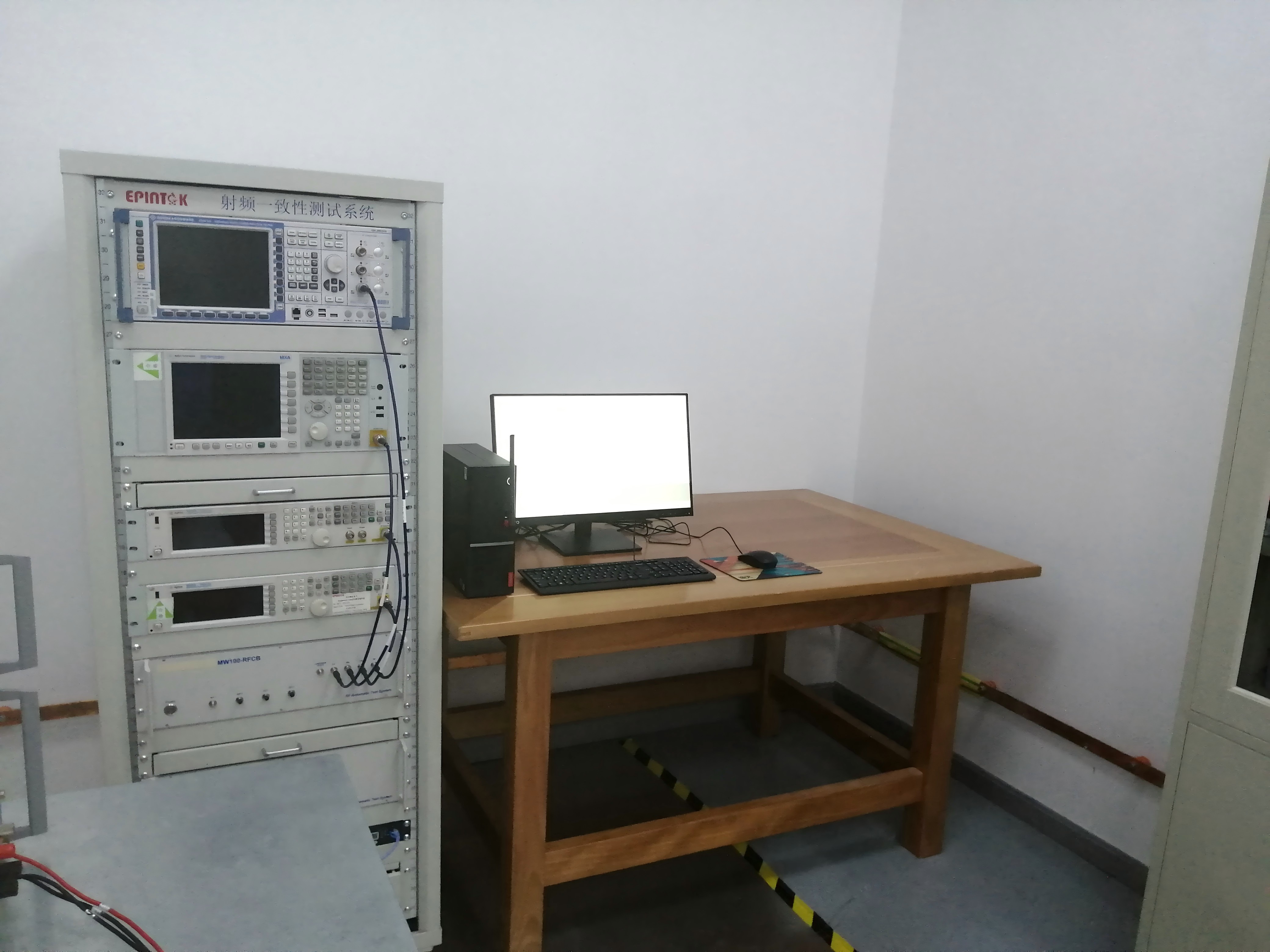
EPINTEK RF Lab is accredited by A2LA, IAS according to ISO/IEC 17025 and maintains one RF test chamber and one RF conducted system to support the RF testing of Wi-Fi, Bluetooth, 2G/3G/4G/5G etc.


Introduction of RF test items
EPINTEK RF Lab is accredited by A2LA, IAS according to ISO/IEC 17025 and maintains one RF test chamber and one RF conducted system to support the RF testing of Wi-Fi, Bluetooth, 2G/3G/4G/5G etc.
The main testing capabilities include all products with wireless functions, such as wearable products, healthcare products with wireless functions, ICT products with wireless functions.
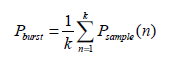
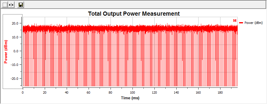
· RF test items | · RF output power | · Definition: The RF output power is defined as the mean equivalent isotropically radiated power (e.i.r.p.) of the equipment during a transmission burst. · Test method: · 1, Sample speed 1 MS/s or faster. · 2, The samples shall represent the RMS power of the signal. · 3, the measurement duration shall be long enough to ensure a minimum number of bursts (at least 10) are captured. · 4, · 5 , P=A+G+Y · | |
· Power Spectral Density | · Definition: The Power Spectral Density is the mean equivalent isotropically radiated power (e.i.r.p.) spectral density in a 1 MHz bandwidth during a transmission burst. · Connect the UUT to the spectrum analyser and use the following settings: · • Start Frequency: 2 400 MHz • Stop Frequency: 2 483,5 MHz • Resolution BW: 10 kHz • Video BW: 30 kHz • Sweep Points: > 8 350; for spectrum analysers not supporting this number of sweep points, the frequency band may be segmented • Detector: RMS • Trace Mode: Max Hold • Sweep time: For non-continuous transmissions: 2 × Channel Occupancy Time × number of sweep points For non-adaptive equipment use the maximum TX-sequence time in the formula above instead of the Channel Occupancy Time For continuous transmissions: 10 s; the sweep time may be increased further until a value where the sweep time has no further impact anymore on the RMS value of the signal.
| ||
· Occupied Channel Bandwidth | · Definition: The Occupied Channel Bandwidth is the bandwidth that contains 99 % of the power of the signal when considering a single hopping frequency. · Step 1: Connect the UUT to the spectrum analyser and use the following settings: • Centre Frequency: The centre frequency of the channel under test • Resolution BW: ~ 1 % of the span without going below 1 % • Video BW: 3 × RBW • Frequency Span: 2 × Nominal Channel Bandwidth • Detector Mode: RMS • Trace Mode: Max Hold • Sweep time: 1 s Step 2: Wait for the trace to stabilize. Find the peak value of the trace and place the analyser marker on this peak. Step 3: Use the 99 % bandwidth function of the spectrum analyser to measure the Occupied Channel Bandwidth of the UUT. This value shall be recorded. Make sure that the power envelope is sufficiently above the noise floor of the analyser to avoid the noise signals left and right from the power envelope being taken into account by this measurement. | ||
· Transmitter unwanted emissions in the out-of-band domain | · Definition: Transmitter unwanted emissions in the out-of-band domain are emissions when the equipment is in Transmit mode, on frequencies immediately outside the necessary bandwidth which results from the modulation process, but excluding spurious emissions. · Step 1: • Connect the UUT to the spectrum analyser and use the following settings: - Measurement Mode: Time Domain Power - Centre Frequency: 2 484 MHz - Span: Zero Span - Resolution BW: 1 MHz - Filter mode: Channel filter - Video BW: 3 MHz - Detector Mode: RMS - Trace Mode: Max Hold - Sweep Mode: Single Sweep - Sweep Points: Sweep time [µs] / (1 µs) with a maximum of 30 000 - Trigger Mode: Video - Sweep Time: > 120 % of the duration of the longest burst detected during the measurement of the RF Output Power | ||
· | · Step 2 (segment 2 483,5 MHz to 2 483,5 MHz + BW): • The measurement shall be performed and repeated while the trigger level is increased until no triggering takes place. • For FHSS equipment operating in a normal hopping mode, the different hops will result in signal bursts with different power levels. In this case the burst with the highest power level shall be selected. • Set a window (start and stop lines) to match with the start and end of the burst and in which the RMS power shall be measured using the Time Domain Power function. • Select RMS power to be measured within the selected window and note the result which is the RMS power within this 1 MHz segment (2 483,5 MHz to 2 484,5 MHz). Compare this value with the applicable limit provided by the mask. • Increase the centre frequency in steps of 1 MHz and repeat this measurement for every 1 MHz segment within the range 2 483,5 MHz to 2 483,5 MHz + BW. The centre frequency of the last 1 MHz segment shall be set to 2 483,5 MHz + BW - 0,5 MHz (which means this may partly overlap with the previous 1 MHz segment). Step 3 (segment 2 483,5 MHz + BW to 2 483,5 MHz + 2 BW): • Change the centre frequency of the analyser to 2 484 MHz + BW and perform the measurement for the first 1 MHz segment within range 2 483,5 MHz + BW to 2 483,5 MHz + 2 BW. Increase the centre frequency in 1 MHz steps and repeat the measurements to cover this whole range. The centre frequency of the last 1 MHz segment shall be set to 2 483,5 MHz + 2 BW - 0,5 MHz (which means this may partly overlap with the previous 1 MHz segment). Step 4 (segment 2 400 MHz - BW to 2 400 MHz): • Change the centre frequency of the analyser to 2 399,5 MHz and perform the measurement for the first 1 MHz segment within range 2 400 MHz - BW to 2 400 MHz Reduce the centre frequency in 1 MHz steps and repeat the measurements to cover this whole range. The centre frequency of the last 1 MHz segment shall be set to 2 400 MHz - BW + 0,5 MHz (which means this may partly overlap with the previous 1 MHz segment). Step 5 (segment 2 400 MHz - 2 BW to 2 400 MHz - BW): • Change the centre frequency of the analyser to 2 399,5 MHz - BW and perform the measurement for the first 1 MHz segment within range 2 400 MHz - 2 BW to 2 400 MHz - BW. Reduce the centre frequency in 1 MHz steps and repeat the measurements to cover this whole range. The centre frequency of the last 1 MHz segment shall be set to 2 400 MHz - 2 BW + 0,5 MHz (which means this may partly overlap with the previous 1 MHz segment). | ||
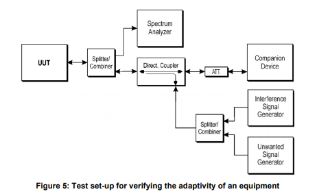
· Adaptivity (Channel access mechanism) | · Definition: Non-LBT based Detect and Avoid is a mechanism for equipment using wide band modulations other than FHSS and by which a given channel is made 'unavailable' because interference was reported after the transmission in that channel. · · Step 1: • The UUT shall connect to a companion device during the test. The interference signal generator, the unwanted signal generator, the spectrum analyser, the UUT and the companion device are connected using a set-up equivalent to the example given by figure 5 although the interference and unwanted signal generator do not generate any signals at this point in time. The spectrum analyser is used to monitor the transmissions of both the UUT and the companion device and it should be possible to distinguish between either transmission. In addition, the spectrum analyser is used to monitor the transmissions of the UUT in response to the interfering and the unwanted signals. • Adjust the received signal level (wanted signal from the companion device) at the UUT to the value defined in table 9 (clause 4.3.2.6.2.2). · Step 2: • Configure the UUT for normal transmissions with a sufficiently high payload resulting in a minimum transmitter activity ratio (TxOn / (TxOn + TxOff)) of 0,3. Where this is not possible, the UUT shall be configured to the maximum payload possible. • Using the procedure defined in clause 5.4.6.2.1.5, it shall be verified that the UUT complies with the maximum Channel Occupancy Time and minimum Idle Period defined in clause 4.3.2.6.2.2. When measuring the Idle Period of the UUT, only transmissions from the UUT shall be considered. · Step 3: Adding the interference signal • An interference signal as defined in clause B.7 is injected on the current operating channel of the UUT. The power spectral density level (at the input of the UUT) of this interference signal shall be equal to the detection threshold defined in clause 4.3.2.6.2.2, step 4. · Step 4: Verification of reaction to the interference signal | ||
· Transmitter unwanted emissions in the spurious domain | · Definition: Transmitter unwanted emissions in the spurious domain are emissions outside the allocated band and outside the out-of-band domain as indicated in figure 1 when the equipment is in Transmit mode. · Step 1: The sensitivity of the measurement set-up should be such that the noise floor is at least 12 dB below the limits given in table 4 or table 12. Step 2: The emissions over the range 30 MHz to 1 000 MHz shall be identified. Spectrum analyser settings: • Resolution bandwidth: 100 kHz• Video bandwidth: 300 kHz • Filter type: 3 dB (Gaussian) • Detector mode: Peak • Trace Mode: Max Hold • Sweep Points: ≥ 19 400; for spectrum analysers not supporting this high number of sweep points, the frequency band may be segmented. • Sweep time: For non continuous transmissions (duty cycle less than 100 %), the sweep time shall be sufficiently long, such that for each 100 kHz frequency step, the measurement time is greater than two transmissions of the UUT, on any channel. For FHSS equipment operating in a normal operating (hopping not disabled) mode, the sweep time shall be further increased to capture multiple transmissions on any of the hopping frequencies. The above sweep time setting may result in long measuring times in case of FHSS equipment. To avoid such long measuring times, an FFT analyser may be used. Allow the trace to stabilize. Any emissions identified during the sweeps above and that fall within the 6 dB range below the applicable limit or above, shall be individually measured using the procedure in clause 5.4.9.2.1.3 and compared to the limits given in table 4 or table 12. Step 3: The emissions over the range 1 GHz to 12,75 GHz shall be identified. Spectrum analyser settings: • Resolution bandwidth: 1 MHz • Video bandwidth: 3 MHz • Filter type: 3 dB (Gaussian) • Detector mode: Peak • Trace Mode: Max Hold • Sweep Points: ≥ 23 500; for spectrum analysers not supporting this high number of sweep points, the frequency band may be segmented | ||
· Receiver spurious emissions · | · Definition: Receiver spurious emissions are emissions at any frequency when the equipment is in receiving mode · Pre-scan The procedure in step 1 to step 4 below shall be used to identify potential unwanted emissions of the UUT. Step 1: The sensitivity of the spectrum analyser should be such that the noise floor is at least 12 dB below the limits given in table 5 or table 13. Step 2: The emissions over the range 30 MHz to 1 000 MHz shall be identified. Spectrum analyser settings: • Resolution bandwidth: 100 kHz • Video bandwidth: 300 kHz • Filter type: 3 dB (Gaussian) • Detector mode: Peak • Trace Mode: Max Hold• Sweep Points: ≥ 19 400 • Sweep time: Auto Wait for the trace to stabilize. Any emissions identified during the sweeps above and that fall within the 6 dB range below the applicable limit or above, shall be individually measured using the procedure in clause 5.4.10.2.1.3 and compared to the limits given in table 5 or table 13. Step 3: The emissions over the range 1 GHz to 12,75 GHz shall be identified. Spectrum analyser settings: • Resolution bandwidth: 1 MHz • Video bandwidth: 3 MHz • Filter type: 3 dB (Gaussian) • Detector mode: Peak • Trace Mode: Max Hold • Sweep Points: ≥ 23 500; for spectrum analysers not supporting this high number of sweep points, the frequency band may be segmented • Sweep time: Auto | ||
· Receiver Blocking · | · Receiver categories: · (1), Adaptive equipment with a maximum RF output power greater than 10 dBm e.i.r.p. shall be considered as receiver category 1 equipment · (2), Non-adaptive equipment with a Medium Utilization (MU) factor greater than 1 % and less than or equal to 10 % or adaptive equipment with a maximum RF output power of 10 dBm e.i.r.p. shall be considered as receiver category 2 equipment. · (3), Non-adaptive equipment with a maximum Medium Utilization (MU) factor of 1 % or adaptive equipment with a maximum RF output power of 0 dBm e.i.r.p. shall be considered as receiver category 3 equipment. · Step 1: • For non-FHSS equipment, the UUT shall be set to the lowest operating channel on which the blocking test has to be performed (see clause 5.4.11.1). Step 2: • The blocking signal generator is set to the first frequency as defined in the appropriate table corresponding to the receiver category and type of equipment. Step 3: • With the blocking signal generator switched off, a communication link is established between the UUT and the associated companion device using the test setup shown in figure 6. • Unless the option provided in note 2 of the applicable table referred to in clause 5.4.11.2.1 is used, the level of the wanted signal shall be set to the value provided in the table corresponding to the receiver category and type of equipment. The test procedure defined in clause 5.4.2, and more in particular clause 5.4.2.2.1.2, can be used to measure the (conducted) level of the wanted signal however no correction shall be made for antenna gain of the companion device (step 6 in clause 5.4.2.2.1.2 shall be ignored). This level may be measured directly at the output of the companion device and a correction is made for the coupling loss into the UUT. The actual level for the wanted signal shall be recorded in the test report. • When the option provided in note 2 of the applicable table referred to in clause 5.4.11.2.1 is used, the attenuation of the variable attenuator shall be increased in 1 dB steps to a value at which the minimum performance criteria as specified in clause 4.3.1.12.3 or clause 4.3.2.11.3 is still met. The resulting level for the wanted signal at the input of the UUT is Pmin. This signal level (Pmin) is increased by the value provided in note 2 of the applicable table corresponding to the receiver category and type of equipment. Step 4: • The blocking signal at the UUT is set to the level provided in the table corresponding to the receiver category and type of equipment. • If the performance criteria as specified in clause 4.3.1.12.3 or clause 4.3.2.11.3 are met then proceed to step 6. Step 5: • If the performance criteria as specified in clause 4.3.1.12.3 or clause 4.3.2.11.3 is not met, step 3 and step 4 shall be repeated after that the frequency of the blocking signal set in step 2 has been increased with a value equal to the Occupied Channel Bandwidth except: - For the blocking frequency 2 380 MHz, where this frequency offset shall be less than or equal to 10 MHz. If this frequency offset is more than 7 MHz, the level of the wanted signal shall be increased by 3 dB. - For the blocking frequency 2 503,5 MHz, where this frequency offset shall be less than or equal to 10 MHz. If this frequency offset is more than 7 MHz, the level of the wanted signal shall be decreased by 3 dB. • If the performance criteria as specified in clause 4.3.1.12.3 or clause 4.3.2.11.3 is still not met, step 3 and step 4 shall be repeated after that the frequency of the blocking signal set in step 2 has been decreased with a value equal to the Occupied Channel Bandwidth except: - For the blocking frequency 2 380 MHz, where this frequency offset shall be less than or equal to 10 MHz. If this frequency offset is more than 7 MHz, the level of the wanted signal shall be decreased by 3 dB. - For the blocking frequency 2 503,5 MHz, where this frequency offset shall be less than or equal to 10 MHz. If this frequency offset is more than 7 MHz, the level of the wanted signal shall be increased by 3 dB. • If the performance criteria as specified in clause 4.3.1.12.3 or clause 4.3.2.11.3 is still not met, the UUT fails to comply with the Receiver Blocking requirement and step 6 and step 7 are no longer required. • It shall be recorded in the test report whether the shift of blocking frequencies as described in the present step was used. Step 6: • Repeat step 4 and step 5 for each remaining combination of frequency and level for the blocking signal as provided in the table corresponding to the receiver category and type of equipment. Step 7: • For non-FHSS equipment, repeat step 2 to step 6 with the UUT operating at the highest operating channel on which the blocking test has to be performed (see clause 5.4.11.1). Step 8: • It shall be assessed and recorded in the test report whether the UUT complies with the Receiver Blocking requirement
|
Standards
SRRC | CE | FCC |
信部无353号 | EN 300 328 | FCC 15.247 |
短距离微功率52号 | EN 300 220-1&-2 | FCC 15.249 |
YDB 086.1-2012,工信部无[2012]436号,工信部无函[2014]314号,工信部无函[2014]313 号 工信部无[2012]436号, YDB 086.1-2012, 3GPP TS 36.521-1 | EN 301 908-1&-25 | FCC part22/24/27/90 |
Lead time:
4-8 weeks per product, depending on the RF specification of EUT.
Copyright © EPINTEK GROUP
Powerd by PEERHI
EPINTEK GROUP
Tel: +86 21 54736833
Address: 4th Floor, T2 Wanjin Center, Lane 360, Xinlong Road, Minhang District, Shanghai
E-mail: stefanie.sun@epintek.com


We Focus on the Demand for Innovation